Working with a Neato Lidar
01 Aug 2018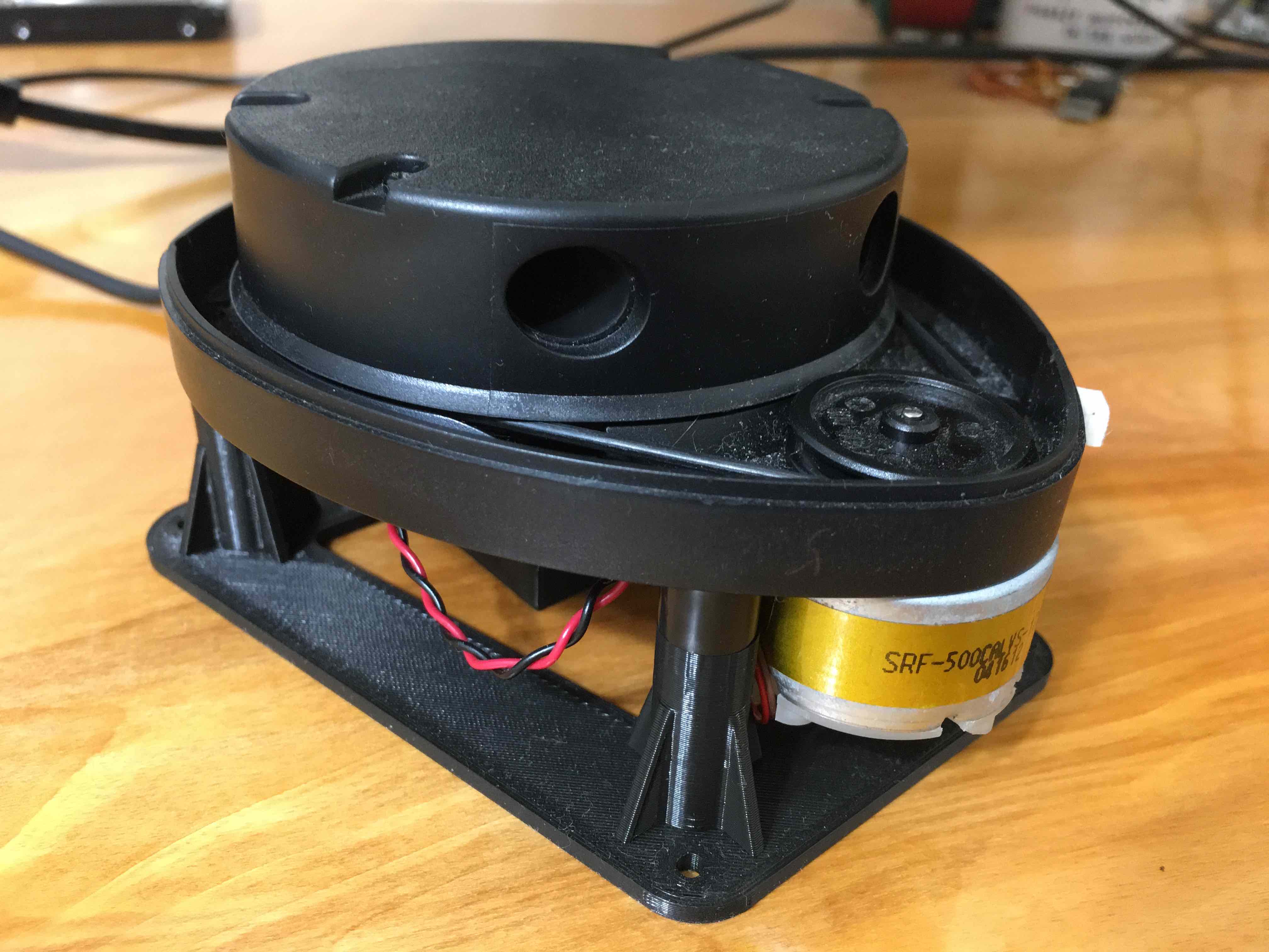 A lidar measures distance to the nearest object in-front of the sensor. For e.g., a lidar mounted on a robot can be used to detect obstacles in the path.
A lidar is more expensive but provides better accuracy and range than other methods such as
ultrasonic sensors
when measuring distance. In my effort to build an autonomous car, I chose to use a Neato robovaccum lidar - XV-11.
In this post I am writing down my experiences of working with it.
A lidar measures distance to the nearest object in-front of the sensor. For e.g., a lidar mounted on a robot can be used to detect obstacles in the path.
A lidar is more expensive but provides better accuracy and range than other methods such as
ultrasonic sensors
when measuring distance. In my effort to build an autonomous car, I chose to use a Neato robovaccum lidar - XV-11.
In this post I am writing down my experiences of working with it.
I ordered a used Neato XV-11 lidar from Ebay after reading this hack-a-day blog. It turned out that writing my own code and building a circuit with Power and Signal separation would take considerable more time than I wanted to spend on measuring distances! Instead, I used a XV-11 controller from GetSurreal, which abstracted away all of the nitty-gritty details of connections and power and gave me a simple USB cable to connect to the lidar over a serial port. Even with the ready-made circuit, it took me a while to get it to work well, hence I am documenting my effort below.
Components
- XV-11 Neato lidar from ebay/amazon ($50 - $100)
- XV-11 controller from Get Surreal ($29). They have released a newer version for the controller since I bought one
- Lidar mount (Optional) from Get Surreal ($9)
- Raspberry pi 3 (Optional) if you want to control lidar from one. Earlier versions of Raspberry Pi do not provide enough current through USB port to run this lidar
Quick start
The default setup of the lidar controller continuously scans 360 degrees and sends data back in the raw format. Get Surreal provides python code to read the values and plot. This codes uses an older version of a python visualization library that has a complex installation on Mac OS. I have modified the code to create distance plots using matplotlib python library that is easier to install and use cross-platform. Code is here.
Make sure python is available on your machine. Next, clone the repo and install the requirements through the requirements.txt
git clone https://github.com/udayankumar/pylidar
cd pylidar
pip install -r requirements.txt
Now connect the lidar to your machine via USB and find out its device name. As an example, on my Macbook, the lidar devices gets mapped to - /dev/cu.usbmodem12341. The device name for you will be different based on the setup and OS. Replace the name of the device in pylidar.py here. Now run the code
python lidar.py
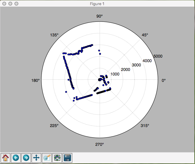
This should open up another windows showing the polar plot like this :
How to read this plot
This is a 2-D polar plot and uses polar coordinates. Each point in this plot can be identified by the angle and the distance from the center. In our case, location of the lidar is the center. The blue dots indicate the location of the object closest to the lidar at that angle. The distance is measured in mm (millimeter). The circles with numbers (1000, 2000, 3000, 4000, 5000) are radial axis labels indicating distance from the center in mm.
What’s next
Since the lidar continuously scans the surroundings, we can now utilize the above code to feed data to a RC car’s navigation algorithm. We have already figured out how to control a RC Car with Raspberry PI. In the next post, I will work towards navigation the RC car using lidar data.
Advance usage
By default the lidar is continuously rotating and sending data for 360 degrees at a preset RPM. With the lidar configuration it is possible to set and save these parameters as described at Get Surreal website. I, however, had difficulty sending commands over a serial terminal to the controller as it would hang upon receiving a lot of data from the controller. I tried Arduino IDE on Mac and Cute Terminal on Raspberry Pi. Whenever I was successful sending the RelayOff command, I was able to interact and configure the controller as mentioned on the sellers website.